|
|
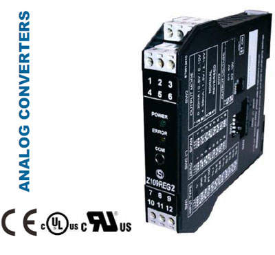
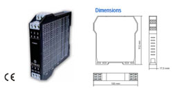
Z-LINE Z109REG2 Universal converter with advanced functions
|
 |
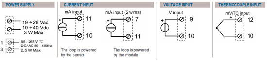
INPUT: voltage (up to ±20 V), current (up to 20 mA), RTD (Pt100, Pt500,
Pt1000, Ni100, KTY81, KTY84, NTC( < 25 KOhm)), TC (J,K,R,S,T,C,B,E,N),
potentiometer, rheostat, |
| STROBE input (control analog output) |
| OUTPUT: current, voltage, relay (SPST) |
| RESOLUTION: programmable from 11 to 15 bits + sign |
| PRECISION: 0.1% |
| RESPONSE TIME: 35 ms (11 bits + sign) |
| ISOLATION: 1.500 Vac @ 3 way |
| POWER SUPPLY: Z109REG2: 9..40 Vdc, 19..28 Vac, Z109REG2-H: 85..265 Vac/Vdc |
|
|
|
S311 AK
Digital display, mA / V input
|
| TECHNICAL DATA |
Z109REG2 • Universal converter with advanced functions
|
 |
ORDER CODE
|
| Model |
Z109REG2 |
Power Supply 10..40 Vdc, 19..28 Vac |
|
Z109REG2-H |
Power Supply 85-265 Vac/Vdc |
| Option |
-ER |
Square root extraction |
| Accessories |
S-TOOL |
Z109REG2 toolkit: setup software
(ZSETUP2) + serial cable (PM001600) |
|
|
|
GENERAL FEATURES
|
| Power supply |
Z109REG2: 9..40 Vdc, 19..28 Vac
Z109REG2-H: 85-265 Vac/Vdc |
| Consumption |
Max 2.5 W; 1.6 W @ 24 Vdc (20 mA output) |
| Isolation |
1.500 Vac @ 3 way |
| Input protection |
Against pulse overvoltages 400 W/ms |
| Output/Supply protection |
Against pulse overvoltages 400 W/ms |
| DIP switch configuration |
Input type, start-end, output mode (zero elevation, scale inversion), output type (mA, V) |
| Software configuration |
Start-end scale, root extraction, burn-out, etc. |
| Status indicators |
Power supply, Out scale, error, alarm |
| Operating temperature |
-10..+60°C |
| Humidity |
Min 30%, max 90% at 40°C non condensing |
| Memory |
EEPROM for all setup data; retention time: 40 years |
| Errors |
V |
mA |
Ohm |
Ni100 |
Pt100 |
Pt500 |
Pt1000 |
KTY81 |
KTY84 |
| Calibration |
0.1% |
0.1% |
0.1% |
0.1% |
0.1% |
0.1% |
0.1% |
0.1% |
0.1% |
| Thermal drift |
0.01%/°K |
0.01%/°K |
0.01%/°K |
0.01%/°K |
0.01%/°K |
0.01%/°K |
0.01%/°K |
0.01%/°K |
0.01%/°K |
| Linearity |
0.05% |
0.05% |
0.02%
(>0°C);
0.05% |
|
|
|
|
|
|
| EMI |
<1% |
<1% |
|
|
|
|
|
|
|
|
| Errors |
TC J |
TC K |
TC R |
TC S |
TC T |
TCB |
TC E |
TC N |
Vout |
| Calibration |
0.1% |
0.1% |
0.1% |
0.1% |
0.1% |
0.1% |
0.1% |
0.1% |
0.3% |
| Thermal drift |
0.01%/°K |
0.01%/°K |
0.01%/°K |
0.01%/°K |
0.01%/°K |
0.01%/°K |
0.01%/°K |
0.01%/°K |
0.01%/°K |
| Linearity |
0.2°C |
0.2°C |
0.5°C |
0.5°C |
|
1.5°C |
0.2°C |
0.2°C |
0.01% |
| EMI |
<1% |
<1% |
<1% |
<1% |
<1% |
<1% |
<1% |
<1% |
|
|
|
|
| CE Norms EN 61000-6-4 / 2002, EN 61000-2-2/2005, EN61010-1
|
INPUT DATA
|
| Voltage input |
9 bipolar scales from 75 mV to 20 V, input impedance 1 MOhm, max resolution 15 bit + sign |
| Current input |
Bipolar scales up tp 20 mA, input impedance 50 Ohm, max resolution 1 mA |
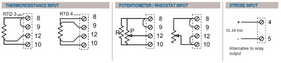
| RTD input |
Pt100, Pt500, Pt1000, Ni100, KTY81, KTY84 and NTC. 3 or 4 wires connection, excitation current 0,65 mA, resolution 0.1°C, RTD or cable
interruption automatic detection. Resistive value for NTC: <25 KOhm. KTY81, KTY84 and NTC settabe only by software. |
| TC input |
TC J,K,R,S,T,B,E,N, resolution: 2,5 mV, TC interruption automatic detection, input impedance > 5 MOhm |
| Potentiometer input |
Excitation voltage 300 mV, input impedance > 5MOhm, potentiometer range from 500 Ohm to 10 kOhm (with parallel resistor 500 Ohm) |
| Rheostat input |
End scale min 500 Ohm, max 25 kOhm |
| Strobe input |
Alternative to relay output |
| Sample frequency |
240 sps (11 bit –+ sign)..15 sps (15 bit + sign) |
| Response time |
35 ms (11 bit + sign)..140 ms (15 bit + sign) |
|
|
|
OUTPUT DATA
|
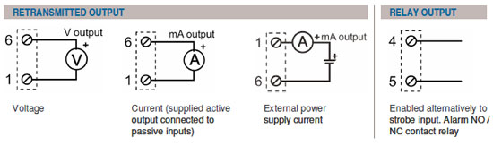
| Current ouput |
Scales: 0..20 / 4..20 mA, max load resistance: 600 Ohm |
| Voltage output |
Scales: 0..5 / 0..10 / 1..5 / 2..10 V, min load resistance: 2kOhm |
| Relay output |
Alternative to strobe input
NC relay contact, NO in case of alarm |
| Resolution |
2,5 mA / 1,25 mV |
| Output retransmission |
Isolated analog output, current / voltage output
Supplied sctive output connected to passive inputs |
|
|
|
|
CONFIGURATION
|
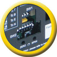
1- DIP-SWITCH
- Input type
- Zero and Span
- Output type
- Scale inversion
|
|
|
CONFIGURATION
|
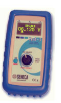
2- HANDHELD
- • Min / max range scale; digital filter; square root extraction
- • Burn-out
- • Analog scale; error analog output value
- • Rejection frequency (50 – 60 Hz)
- • Sampling time / Resolution
- • Measure 2, 3, 4 wires for RTD
- • Relay alarm control, strobe configuration
|
|
|
CONFIGURATION
|
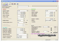
3- SOFTWARE
- • Min / max range scale; digital filter; square root extraction
- • Burn-out
- • Analog scale; error analog output value
- • Rejection frequency (50 – 60 Hz)
- • Sampling time / Resolution
- • Measure 2, 3, 4 wires for RTD
- • Relay alarm control, strobe configuration
|
|
|
|
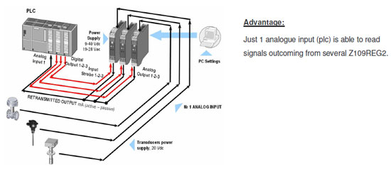
| APPLICATION EXAMPLES |
MULTIPLEXER
|
|
|
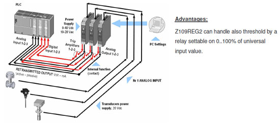
TRIP AMPLIFIER
|
|
|
|
|
Ucontrol Pty Ltd ABN 18 150 270 161 Site last updated 18.10.2016 Contact the Webmaster |Signal Converter | Universal Signal Converter
|
|
|